
Design, art, and architecture
Repeat-free ornamental surfaces, facades, textiles, and real-world tiling instructions.
One shape, no repeating motif
Historic zellige, azulejo, and parquet crafts fought monotony with hand variation. Industrial printing and molding made exact repeats cheap, and made wallpaper repeats obvious at wall scale. An aperiodic monotile restores structure without a translational repeat unit: one manufactured outline, arrangements that cannot tile by lattice translation, proved rather than promised.[2][3] More finished stills and loops live on the art page.
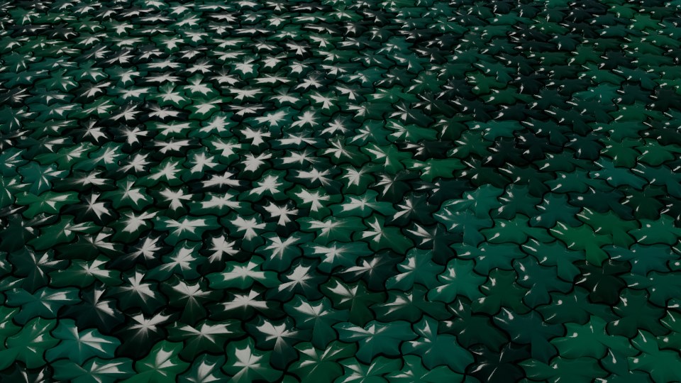
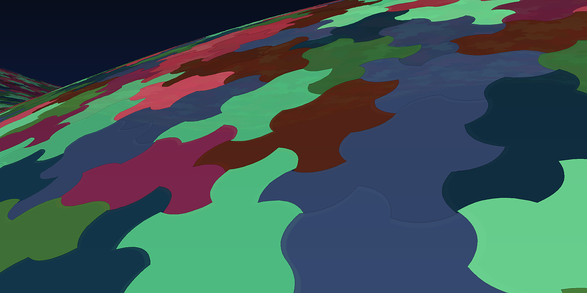
Because the tiling is deterministic, a designer can sign off on the exact layout before fabrication, every tile position is known, exportable, and reproducible. And because Tile(1,1) needs no reflected copies, a homochiral design can avoid a second mirrored outline. Whether production can use one mold, die, or glaze workflow depends on edge treatment, finish, and process.[2]
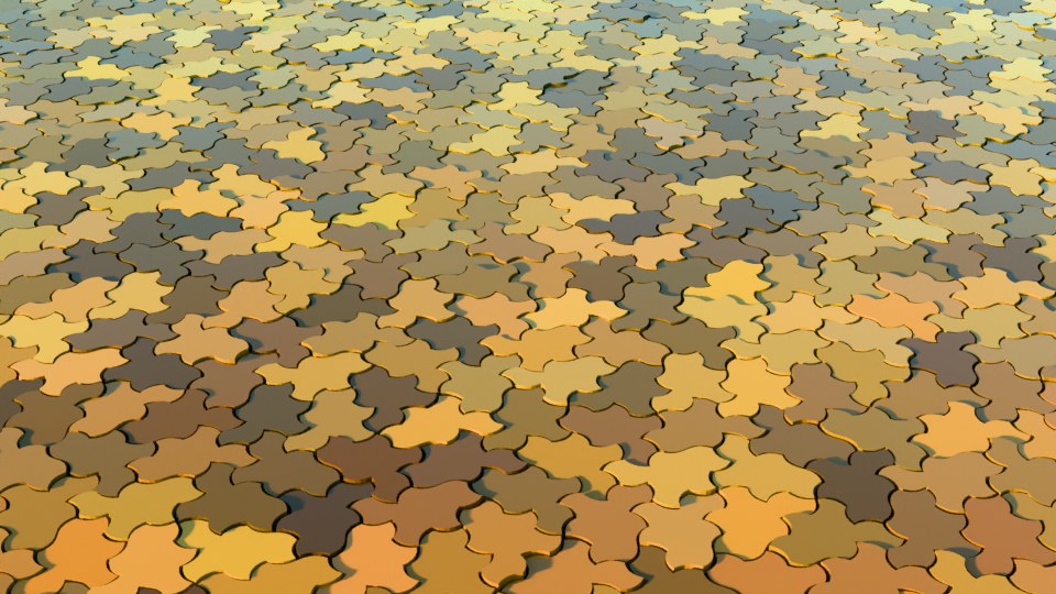
Tiling a real surface: practical instructions
Physical monotile installations are already common among mathematicians, makers, and a growing number of tile artisans. The working recipe, distilled from the research community's own guides:
- Choose the geometry for the manufacturing constraint. Hat tilings require reflected copies, so one-sided glazed or finished parts become two SKUs. Homochiral Spectre or Tile(1,1) layouts avoid that second outline when the process cannot flip parts. If both faces are identical, Hat may still be acceptable. The choice is a manufacturing tradeoff, not a universal Spectre preference.[1][2]
- Prefer curved or keyed edges when installers must not invent periodicity. The straight-edged Tile(1,1) can be assembled into a periodic pattern by a well-meaning installer using both handednesses. Curved Spectre edges physically refuse periodic and reflected placements, the geometry enforces correctness.[2]
- Get the outline from a trusted source. Kaplan's project page publishes SVG outlines; community repositories provide OpenSCAD, STL, and DXF for 3D printing, laser cutting, and CNC (see the bibliography tools list). Parametric models let you add orientation marks so pieces cannot be laid face-down.
- Assemble by supertile. Working tile-by-tile invites dead ends. Pre-assemble the 8-to-9-tile clusters from the substitution system, then place clusters, the same hierarchy the mathematics uses. See Substitution tiling.
- Or skip layout entirely: generate the exact patch for your wall's dimensions with a clipping mask at aperiodicgenerator.com, and deliver the installer a numbered plan where every tile has an ID and position.
Coates studies hexagonal quasiperiodic decorations of periodic lattices as a transferable geometric precedent; vertices may remain periodic while bonds are quasiperiodic.[18] The cited work does not prove a coherent periodic-Spectre interface, so a Spectre handoff still requires an explicit boundary coding, metric fit, tolerance study, and physical validation.
Composition, color, and scale
The outline supplies structure, not a finished composition. Color can follow tile orientation, substitution parent, distance from a focal point, or a small constrained palette. Use hierarchy labels for broad fields and per-tile IDs for fine variation; this preserves visual continuity without inventing a repeat unit. Mock up the full elevation or floor at viewing distance, because dense joints and high contrast can dominate the shape.
Jowers and Moat expose another design layer by connecting selected Hat-family vertices with straight segments. The resulting subsidiary systems contain mostly convex polygons aligned with larger metatile structure, opening alternatives for color fields, screens, and multi-part assemblies.[66] Some newly proposed derivatives are described by their authors as assumed aperiodic rather than proved, so geometric exploration must not be promoted as a new monotile theorem.
- Feature walls, floors, and facades with provable non-repetition, including built limestone terraces assembled from hundreds of waterjet-cut Spectre pieces (see bibliography)
- Mathematically constructed three-dimensional topological-interlocking systems made from identical aperiodic blocks; physical load testing remains open[50]
- Generative sculpture, ornamental screens, and visual illusions
- Textiles, wallpaper, packaging, embossing, and engraving with no repeat unit
- Lightweight shells, tensile structures, and spatial studies for built environments
Lifted wall modules and interfaces
Van Dongen’s Lifted Aperiodic Hat and Turtle replaces each double-kite with a polyhedral surface module, then glues modules into congruent three-dimensional Hat or Turtle units. The resulting assemblies can carry a continuous non-periodic wall texture; paper layouts and an alternate square-grid lift make the geometry reproducible.[69]
This is a geometric and artistic construction, not structural engineering and not Nan Ma’s ℝ⁴ edge lift. It reports no load, joint, weathering, fire, drainage, code, tolerance, or scale tests. Likewise, Coates’s periodic-aperiodic interfaces are methodological precedent rather than proof that a periodic wall can meet a Spectre field coherently without a separately designed boundary map.[18]
Fabrication and installation planning
Freeze the canonical outline, units, handedness, joint width, and boundary policy before nesting parts. Number pieces or clusters on the drawing and on removable labels. Dry-fit substitution clusters, survey cumulative error, then install from fixed datums rather than following a drifting edge. Record partial boundary pieces separately from whole tiles and reserve spares by orientation.
For floors and walls, account for substrate flatness, adhesive bed, grout movement joints, drainage, cleanability, slip resistance, fire behavior, weathering, and replacement access. Structural facades require an independent support and fastening design; the mathematical tiling is not a building system. Built terraces and community installations show that physical assembly is feasible. Coates’s periodic-aperiodic interface work is precedent for boundary design, not a validated Spectre installation recipe.[18]
Constraints and open design questions
A single outline does not guarantee one mold, lower cost, code compliance, or easy replacement. Curved edges may increase cutting time; one-sided finishes can create handed inventory; small acute features may chip; and clipped boundaries can dominate waste. Compare nesting yield, tool time, part count, installer error, maintenance access, and total installed cost with a conventional module.
Ornament, tested mechanical lattices, and proposed architectural shells are different evidence levels. Describe a built installation as built, a simulation as simulated, and an untested facade or textile concept as a candidate direction.
See also
Computer graphics, Materials and fabrication
Categories: Applications